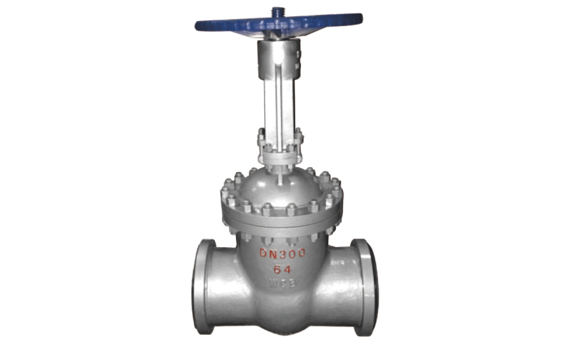
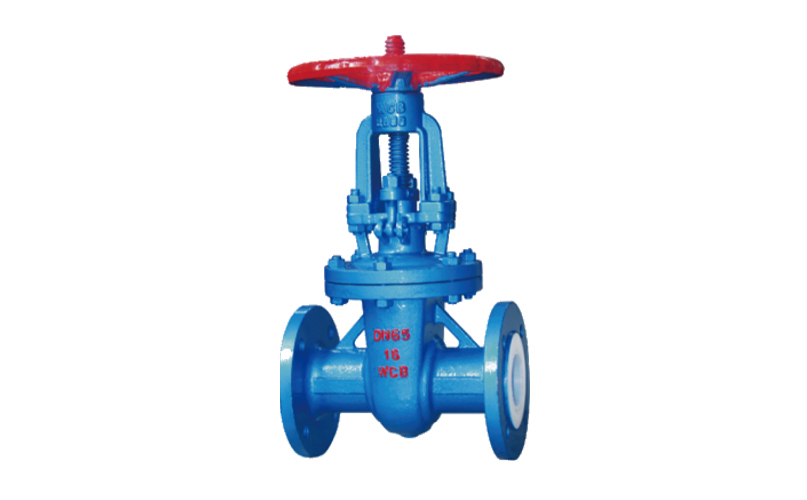
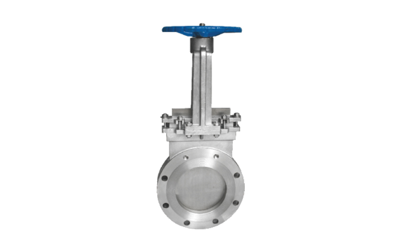
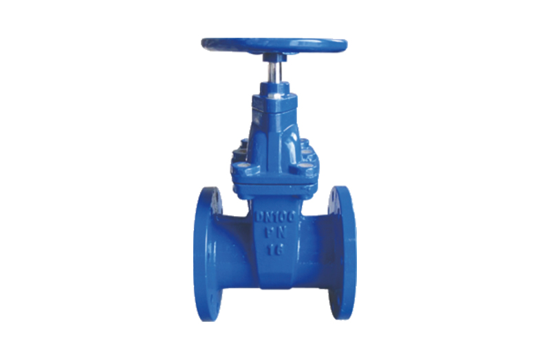
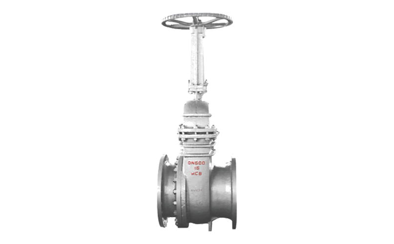
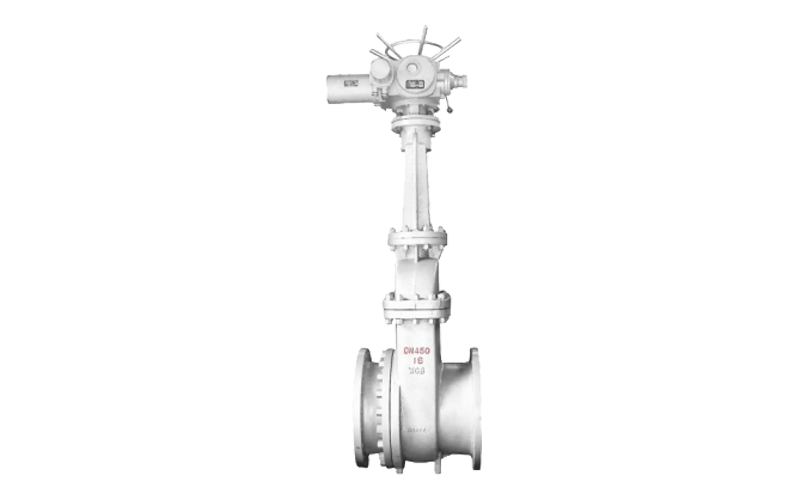
Slag Discharge Gate Valve

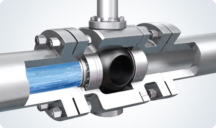
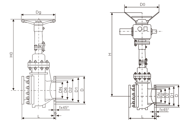
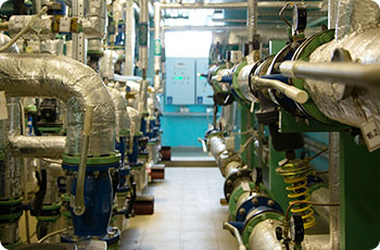
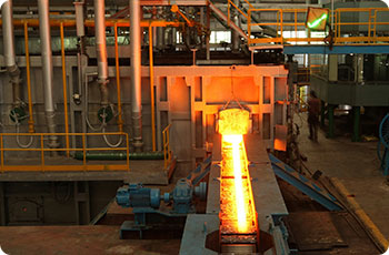
Slag discharge gate valve is an industrial valve designed to control the on/off of pipeline media containing solid particles such as ash, slurry, and slag water mixtures. The valve body is made of wear-resistant materials (such as engineering ceramics or hardened alloys) and designed with anti blocking flow channels (such as straight through/Y-shaped structure+slag guide groove), which can withstand PN1.6-PN6.4 pressure and 0-100 ℃ working conditions. It is widely used in systems that require the treatment of two-phase flow media such as thermal power generation and mining beneficiation. Compared to ordinary gate valves, it has stronger wear resistance and anti sedimentation ability.

  • Maintain convenience and economy
  • High temperature resistance and corrosion resistance
  • Diversified driving adaptation
  • Enhanced sealing structure
  • Anti clogging flow channel design
  • Application of high wear-resistant materials
Maintain convenience and economy
  • Maintain convenience and economy
    01
    Modular design allows for quick replacement of ceramic valve cores and sealing components, reducing maintenance time by over 50%; The flow resistance coefficient is as low as 0.02-0.03, which reduces pressure loss by 30% compared to traditional valves and significantly saves energy consumption.
High temperature resistance and corrosion resistance
  • High temperature resistance and corrosion resistance
    01
    Temperature tolerance range -29 ℃~450 ℃, acid and alkali corrosion resistance (pH 0-14), suitable for strong acid, strong alkali and salt spray environments, avoiding electrochemical corrosion problems of metal valves.
Diversified driving adaptation
  • Diversified driving adaptation
    01
    Supports manual, electric, and pneumatic drive, with electric control response time<1 second and opening error ≤ 1mm, meeting the requirements of remote precise adjustment. Some models use bevel gear transmission to improve the convenience of operation under high torque conditions.
Enhanced sealing structure
  • Enhanced sealing structure
    01
    Ceramic ceramic or ceramic metal hard seal combination, utilizing medium pressure to self enhance sealing performance, with a pressure resistance of PN16-PN40; Protect lip patent technology to prevent hard objects from cutting and cracking the sealing ring, and support bidirectional sealing.
Anti clogging flow channel design
  • Anti clogging flow channel design
    01
    Full bore straight through or Y-shaped flow channel structure to avoid dead corners in medium flow; A slag guide groove is installed at the bottom of the valve body to automatically remove slag slurry and reduce the risk of particle accumulation. The split valve body design facilitates quick removal and replacement of ceramic lining, reducing maintenance time.
Application of high wear-resistant materials
  • Application of high wear-resistant materials
    01
    Using engineering ceramics such as aluminum oxide (Al₂O₃) and silicon carbide (SiC), the hardness reaches HRA88 or above, the wear resistance is 5-10 times that of ordinary metal valves, and it can withstand the erosion of media containing 30% -60% solid particles. Some models achieve ceramic and metal matrix composites through hot pressing or inlay processes, balancing toughness and wear resistance.
Main Component Materials

Part Name

Material

valve body

WCB+wear-resistant alloy

valve cover

WCB

support

WCB

ram

WCB+wear-resistant alloy

valve stem

2Cr13

valve seat

WCB+wear-resistant alloy

sealing ring

Enhanced flexible graphite

filler

Enhanced flexible graphite

stem nut

ZCuZ110Fe3

Performance Specifications & Dimensions
  • Nominal Pressure PN
    1.0/1.6/2.5/4.0/6.4/10.0/16.0
  • Shell F
    Px1.5
  • Sealing Pressure
    Px1.1
  • Medium
    Ash water mixture slag water ratio 1:6, maximum particle size ≤ 50mm
  • Temperature (℃)
    ≤150℃

Nominal Diameter
DN(mm)

Main external dimensions and connection dimensions (mm)

L

D

D1

D2

D6

b

f

z-Φd

H

H0

D0

Dg

PN1.6MPa

50

250

160

125

100

-

20

3

4-18

-

335

250

250

80

280

195

160

135

-

22

3

4-18

-

510

280

280

100

300

215

180

155

-

22

3

8-18

-

685

300

300

150

350

280

240

210

-

24

3

8-23

-

790

350

350

200

400

335

295

265

-

26

3

8-23

-

885

350

350

250

450

390

350

320

-

28

3

12-23

-

1015

400

400

300

500

440

400

368

-

28

4

12-23

-

1190

450

450

350

550

500

460

428

-

30

4

16-23

-

1350

500

500

400

600

565

515

482

-

32

4

16-25

-

1460

500

500

450

650

615

565

532

-

32

4

20-25

-

1620

550

550

500

700

670

620

585

-

34

4

20-25

-

1800

550

550

600

800

780

725

685

-

36

5

20-30

-

2030

650

-

700

900

895

840

800

-

40

5

24-30

-

2230

700

-

Note: The pressure range is 1.0MPa~16.0MPa. The above data is for reference only. Please consult the company's sales department for details.

Valve Application
  • Oil & Gas Transportation

    Oil and gas transportation involves multiple modes such as pipelines and ships, and is the core link of the energy supply chain.

  • Chemical Raw Material Control

    The control of chemical raw materials covers the entire process of mining, storage, and production, ensuring safety and process stability.

  • High Temperature SteamPipeline in Power System

    High temperature steam pipelines are the core of energy transmission in power systems, supporting the efficient operation of thermal and nuclear power plants.

  • Other Industries

    Valves control fluids in multiple industries such as new energy and electronics, ensuring safe and efficient production.

Related Recommendations
Always Connect With Us.
24-hour online response, professional team to answer all your questions, Welcome to contact us to customize your exclusive solution.
WeChat
Scan the QR Code with WeChat